Help me with 5link wiring

The place for all things Losi.

Moderators: scr8p, klavy69

Post Reply
User avatar
Cpt.America
Approved Member
Posts: 80
Joined: Tue Jun 15, 2010 1:09 pm
Location: Western WA State, U.S.A

Help me with 5link wiring

Post by Cpt.America »

So, I'm ready to finish up my wiring on my 5link, and need some help with my novak T4, and motor wiring. Where I have the speedo mounted makes things a bit difficult, but i know iv seen them mounted here before. See picture:

1) The motor wires don't reach the motor, so I will need to use a plug? Modern day deans?

2) The servo wire doesn't reach the receiver, unless it goes straight across the battery. I know I could use an extension, but would a modern day extension fit with a period correct shelf queen?

3) battery plug... should I go modern day deans?

Image
- Team Fantom Racing - www.fantomracing.com -

User avatar
Coelacanth
Approved Member
Posts: 7370
Joined: Thu Jul 29, 2010 6:20 pm
Location: Alberta, Canada
Has thanked: 16 times
Been thanked: 288 times

Re: Help me with 5link wiring

Post by Coelacanth »

Here are some suggestions:

-Lose the Tamiya connectors for the ESC/motor and solder on some 3.5mm bullet connectors. They have a lot less resistance, are a lot less bulky, are easy to solder, and the biggest reason why I stopped doing that: What do you do if you find your motor rotation is reversed? :? With bullets, you just disconnect and reconnect them the opposite way to reverse the polarity. With Tamiya connectors, you have to completely disassemble them, reverse the wiring inside, and reassemble them.

-For ESC-to-battery connections, consider EC3 connectors. They're much easier to solder than Deans, almost no chance of shorting the battery leads while soldering, don't require 3 hands to solder, don't need heatshrink, and it's impossible to reverse-connect them--with Deans, it's possible to insert the connectors together enough to short the battery.

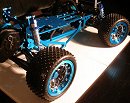
Nice, clean car so far!
Completed projects: CYANide Onroad Optima | Zebra Gold Optima | Barney Optima | OptiMutt RWD Mid
Gallery - Coel's Stalls: Marui Galaxy & Shogun Resto-Mods | FrankenBuff AYK Buffalo | 1987 Buick GNX RC12L3

User avatar
highwayracer
Approved Member
Posts: 1187
Joined: Wed Dec 12, 2007 9:43 pm
Location: Illinois, USA
Been thanked: 3 times

Re: Help me with 5link wiring

Post by highwayracer »

The wire from the ESC doesn't look original...it may have been replaced and shortened by the previous owner. I remember people putting their ESCs on the tower back in the day...it might get you closer to the motor and the receiver.

The other option would be to turn the ESC so that the motor and battery wires are facing the front of the car. You'll get about an inch and a half more on the wire (to the receiver). You can always run a longer wire cominf from the motor.

User avatar
slapshot1979
Approved Member
Posts: 928
Joined: Wed May 26, 2010 6:18 pm
Location: GTA Ontario,Canada

Re: Help me with 5link wiring

Post by slapshot1979 »

I agree with both guys, I always mounted the esc on the rear shock tower. and by fluke I was just going thru an old RCCA book and they had a cutout to make your own shelf to mount the esc on the shock tower horizontally. (LMK if you want it). I would solder motor wires direct if you plan on running this motor exclusivly, or go with bullets or Deans are quite common on motors.
Nice buggy.
Some guys try and keep their stuff balanced on chassis. but you could always add a few Grams of weight to compinsate, if thats your thing
Sleeps with a night light on, not because he's scared of the dark but because the dark is scared of him...........stay thirsty my friends

User avatar
scr8p
Administrator
Posts: 16524
Joined: Tue Feb 07, 2006 9:46 pm
Location: Northampton, PA
Has thanked: 28 times
Been thanked: 957 times

Re: Help me with 5link wiring

Post by scr8p »

replace the 2 upper tower mounting socket cap screws with button head screws (or countersink the tower and use flat head screws) and mount it on the tower.

User avatar
JK Racing
Super Member
Posts: 4603
Joined: Thu Jul 19, 2007 2:32 pm
Location: Placentia, CA
Has thanked: 103 times
Been thanked: 200 times

Re: Help me with 5link wiring

Post by JK Racing »

that servo wire definitely isnt stock novak. they always used braided red/white/black, not yellow. since the car is a shelfer only, the tamiya plugs dont hurt it at all, but a nice set of old 4 pin deans (black are older than the red) would be period correct (at least that is what I used in the late 80s). if you do find 2 sets of 4 pin deans, use one set on the motor to esc and one set on the esc to battery.

:edit: the 4 pin deans are still available :)
Attachments
4 pin deans.jpg
--Joey --
Vintage A&L and Factory Works
Old School Racer & Vintage RC Car nut
JKRacingRC.com

User avatar
Cpt.America
Approved Member
Posts: 80
Joined: Tue Jun 15, 2010 1:09 pm
Location: Western WA State, U.S.A

Re: Help me with 5link wiring

Post by Cpt.America »

1. Thanks for the tips guys... you keep saying the wires aren't orginal, but I just opened the T-4 speedo new in the package myself. It had never been touched, heat sinks never even pressed on... 100% brand spakin new. Either way, how do I get the receiver wire over to the receiver if i don't go across the top? Extension and go in front of the battery hold-down? Of if i flip the speedo, should I just run the receiver wire under the battery between the cells?

2. Where can i get the black 4 pin deans? I remember running those way back in the day, but they were red.

3. I think I want to keep the speedo on the chassis, as i think it looks much better.
- Team Fantom Racing - www.fantomracing.com -

User avatar
Cpt.America
Approved Member
Posts: 80
Joined: Tue Jun 15, 2010 1:09 pm
Location: Western WA State, U.S.A

Re: Help me with 5link wiring

Post by Cpt.America »

- Team Fantom Racing - www.fantomracing.com -

User avatar
JK Racing
Super Member
Posts: 4603
Joined: Thu Jul 19, 2007 2:32 pm
Location: Placentia, CA
Has thanked: 103 times
Been thanked: 200 times

Re: Help me with 5link wiring

Post by JK Racing »

i believe those are the original ones....(deans)

for the novak, here is a pic straight from their site (knowing it is a 1, not a 4), see the wiring is braided and not yellow.

was that NIP refurb or NIP original?
Attachments
nesc1_1.jpg
nesc1_1.jpg (10.26 KiB) Viewed 1152 times
nesc1_1.jpg
nesc1_1.jpg (10.26 KiB) Viewed 1152 times
--Joey --
Vintage A&L and Factory Works
Old School Racer & Vintage RC Car nut
JKRacingRC.com

User avatar
Cpt.America
Approved Member
Posts: 80
Joined: Tue Jun 15, 2010 1:09 pm
Location: Western WA State, U.S.A

Re: Help me with 5link wiring

Post by Cpt.America »

JK Racing wrote:i believe those are the original ones....(deans)

for the novak, here is a pic straight from their site (knowing it is a 1, not a 4), see the wiring is braided and not yellow.

was that NIP refurb or NIP original?
It's a Novak T-4...
- Team Fantom Racing - www.fantomracing.com -

User avatar
JK Racing
Super Member
Posts: 4603
Joined: Thu Jul 19, 2007 2:32 pm
Location: Placentia, CA
Has thanked: 103 times
Been thanked: 200 times

Re: Help me with 5link wiring

Post by JK Racing »

I didnt see any pictures of the "T" series, knowing there were only internal changes from the original numbered series. Even my new GTB2 has the braided red/white/black wire. Let me see if I still have a T4 around somewhere to shoot pictures of.

Either way, if you use a motor plug instead of direct wire, you can spin the speedo around and run it under the battery pack, maybe a piece of black tape to hide it some (since this is a gorgeous shelfer).
--Joey --
Vintage A&L and Factory Works
Old School Racer & Vintage RC Car nut
JKRacingRC.com

User avatar
8rad
Approved Member
Posts: 799
Joined: Fri Feb 13, 2009 3:29 pm
Location: Ottawa, Canada

Re: Help me with 5link wiring

Post by 8rad »

If you shift the speedo back 3/4 inch can you run the wire around the side and under the battery?

Also, I just noticed, if you rotate the receiver 90deg so the antenna is facing the front you may be able to get an extra 1/4 inch on the speedo wire. It may just be enough.

Another option would be to buy a longer lead. You would of course need some soldering skillz. I think an extension is the wrong choice on such a clean buggy.

M2C
"It's not broken, it's British!"

User avatar
Cpt.America
Approved Member
Posts: 80
Joined: Tue Jun 15, 2010 1:09 pm
Location: Western WA State, U.S.A

Re: Help me with 5link wiring

Post by Cpt.America »

Thanks for the help guys... I think I have it planned out now... going to look gorgeous when all done (the entire car front to back is never-run). I too think an extension would be the wrong way to go.

FYI, even the picture of the novak T-4 on novak's website shows this type of yellow/red/black servo wire. I went through the pictures of all the vintage speedos, and it looks like the T-4 is the only speedo to have this type of servo wire... all the others have the braided/twisted style.

http://www.teamnovak.com/timeline/large_timeline_jpgs/nesc_t4_1.jpg
- Team Fantom Racing - www.fantomracing.com -

User avatar
huminski
Approved Member
Posts: 319
Joined: Mon Sep 12, 2011 10:22 am
Location: South Jersey
Has thanked: 1 time
Been thanked: 8 times

Re: Help me with 5link wiring

Post by huminski »

The T-4 wiring from the factory is exactly as the OP's ESC appears, I have a few of them and they are all the same, red and black twisted (not braided) wire to the switch and a flat yellow / red / black wire to the rec. Even the T1 pic that was posted up above has a flat wire to the ESC, though it appears black/black/red in the pic. Only the switch wire is twisted, again, not braided.

Good luck with that car. Your best bet is to make or find an ESC tray that mounts the ESC over the battery, attached to the shock tower as mentioned.

User avatar
GJW
Approved Member
Posts: 2325
Joined: Mon Oct 15, 2007 7:22 pm
Location: AUSTRALIA!!
Been thanked: 1 time

Re: Help me with 5link wiring

Post by GJW »

i would be re-wiring the lead coming from the esc, soldering new wire into the circuit board can be tricky if your new to it. its easy to cut the wire with some extra length with in the orange case, slip some very fine heatshrink over the ends and attach the new lead any excess length can be pushed back through the rubber grommet, jobs done :)

Post Reply

Create an account or sign in to join the discussion

You need to be a member in order to post a reply

Create an account

Not a member? register to join our community
Members can start their own topics & subscribe to topics
It’s free and only takes a minute

Register

Sign in

  • Similar Topics
    Replies
    Views
    Last post
  • Help me deck out my 5link Shelf Queen with electronics
    by Cpt.America » » in Losi Forum
    8 Replies
    1252 Views
    Last post by XxRONNxX
  • What wiring do you use?
    by Coelacanth » » in Kyosho Forum
    6 Replies
    850 Views
    Last post by Coelacanth
  • I need some wiring help please
    by nvxwax » » in Modern Electronics
    7 Replies
    919 Views
    Last post by nvxwax
  • Tekin re-wiring.
    by Dr. Robotnik » » in Vintage Electronics
    18 Replies
    1652 Views
    Last post by Dr. Robotnik
  • BRUSHLESS WIRING HELP
    by FasterLouder » » in Modern Electronics
    4 Replies
    496 Views
    Last post by FasterLouder
  • KO servo wiring.
    by juicedcoupe » » in Vintage Electronics
    1 Replies
    233 Views
    Last post by Frankentruck
  • Receiver wiring help
    by HairTrigger » » in Vintage Electronics
    4 Replies
    1208 Views
    Last post by SiRacer420
  • RC10 wiring?
    by jackflak » » in Temple's RC10 Tech Forum
    28 Replies
    3374 Views
    Last post by GoMachV

Return to “Losi Forum”

Who is online

Users browsing this forum: No registered users and 16 guests