Page 1 of 1
Novak1 repair attempt
Posted: Fri Sep 15, 2023 4:45 pm
by radioactivity
I was reading a thread "Repairing Novak 4 esc _ what tools and what parts?" and it got me to thinking.
When originally building my TOMSE I wanted to use my Novak1 ESC only later to find out it was not working.
First I tried to look for any info on early Novak repairs and pretty much drew a blank.
The ESC showed no visible signs of parts that had failed.
When in a system with a known good receiver, servo, motor and battery the servo did work.
When first turning on the on/off switch to the on position, the motor does spins very briefly.
No amount of adjustments to the ESC could show any signs of life to the motor.
So may thoughts went like this.
1. Replace the parts that heaviest current draw e.g. the 7 BUZ11 FETs and the 1 L7806C-V voltage regulator.
Before pic of back side of PC board
After replacing FETs
Well that did not work


but not totally unexpected.
Next thought will be what the most sensitive component might be.
So I'm setting my sights on the Mitsubishi M51660L "semiconductor integrated circuit for use in servo motor control in radio control applications".
12 of the 14 pins are used in the ESC.
And if I said I found it a bit of a challenge to desolder this I wouldn't be lying.
Arrows denote where IC was soldered.
IC is ordered.
All thoughts are welcome
Chuck
Re: Novak1 repair attempt
Posted: Fri Sep 15, 2023 4:49 pm
by GoMachV
The most common thing I experienced working in the hobby shop was the bec going out inside the escs. If you hook up an external battery and either take out the red lead to the receiver or just leave the switch in the off position, with a good or bad bec the esc should operate normally. We used to do some funky jumpering with an external BEC to get the customer going again without spending a lot on a new esc.
Now that I think about it tho you said the servo works so the bec is obviously working. Doh.
Re: Novak1 repair attempt
Posted: Fri Sep 15, 2023 4:53 pm
by radioactivity
I tried to cover all my bases first but could have easily overlooked some thing.
So, like usual, I dove in head first.
I am definitely not an EE.
Thanks though.
Chuck
Re: Novak1 repair attempt
Posted: Fri Sep 15, 2023 5:12 pm
by JosephS
radioactivity wrote: ↑Fri Sep 15, 2023 4:45 pm
I was reading a thread "Repairing Novak 4 esc _ what tools and what parts?" and it got me to thinking.
I took a real good look and decided that needs to be done '
later'
Re: Novak1 repair attempt
Posted: Sat Sep 16, 2023 12:55 pm
by juicedcoupe
Could be a bad potentiometer.
I have a Futaba esc that acts stupid, kinda like that.
Re: Novak1 repair attempt
Posted: Sat Sep 16, 2023 4:11 pm
by radioactivity
That is a good thought Juicedcoupe.
I just tried to see if there were any glitches to be found.
I could only read the 100k on the right (speed end point) pot. It seems fine even in the circuit.
Can't read left neutral pot, but it does vary when turning the pot.
Both pots do feel surprisingly smooth for the age of the ESC.
I had tried rotating both pots when the ESC was powered on with the trigger pulled but the motor did not respond at all.
Thanks for the tip though!
Chuck
Re: Novak1 repair attempt
Posted: Sat Sep 16, 2023 4:25 pm
by Frankentruck
If there's something wrong with the white/signal wire, like at the receiver end, the ESC won't be available to run the motor. I had an ESC that was similar and was fixed by replacing and re-terminating the red/white/black connector plug.
Re: Novak1 repair attempt
Posted: Sat Sep 16, 2023 10:24 pm
by radioactivity
Thanks Frankentruck
This is the 2nd receiver the Novak1 has been on and I tried it in the servo slot as well. Both of those receivers work with other ESCs but not the Novak1.
So I just ohmed out the 3 wires from the ESC to the receiver plug and they all check OK.
I had replaced the 3 wire harness from the ESC to the receiver so the plug and terminals should have been good. Never hurts to double check.
Thanks again for the input.
Chuck
Re: Novak1 repair attempt
Posted: Sun Sep 17, 2023 8:45 pm
by radioactivity
I took a couple more pics. One of the IC and a better pic of the board without the IC installed.
With the IC removed the and the voltage regulator moved up the second pic also shows 3 small transistors marked 2785. One faces the forward and the two on the left face the larger FETs.
According to what I find is that they are 2SC2785 transistors.
Chuck
Re: Novak1 repair attempt
Posted: Mon Sep 25, 2023 4:41 pm
by radioactivity
I have found some interesting quirks with this ESC.
If anyone has a Novak NESC1 or NESC1x and can take a picture, it might solve my problem.
After replacing the IC there was no difference
However I did find the pinouts on the IC
The #5 pin apparently shows the input. This should be from the receiver???
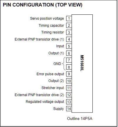
- novak1.15.JPG (33.18 KiB) Viewed 625 times
- novak1.15.JPG (33.18 KiB) Viewed 625 times
A close look at the board shows no wire or trace going to this pin???
Also the output wire from the receiver is connected to the cathode of the zener and then goes to ground on one leg of a resistor?????
I think someone else may have been trying their hand at repair.
Chuck
Re: Novak1 repair attempt
Posted: Mon Sep 25, 2023 5:04 pm
by Frankentruck
Re: Novak1 repair attempt
Posted: Mon Sep 25, 2023 5:27 pm
by radioactivity
Thanks so much Frankentruck!!!!
Can you see the open hole that is near the #5 leg of the IC? Or is there some thing else there.
It is blocked by the blue "lollypop" looking blue capacitor.
and if you can a pic of the other side of the board
Thanks again so much!
Chuck
Re: Novak1 repair attempt
Posted: Mon Sep 25, 2023 5:49 pm
by Frankentruck
Re: Novak1 repair attempt
Posted: Mon Sep 25, 2023 6:29 pm
by radioactivity
Thanks again!
Interesting... The white signal wire is connected to the #5 on the IC.
But only by soldering across 2 separate copper pads. This is shown in your pic inside the red oval that I drew.
Pic taken showing no connection between white wire output signal from receiver to #5 input to IC on PC board.
Chuck