Novak1 repair attempt

Brushed, nicad, radios, etc...

Moderators: scr8p, klavy69

User avatar
radioactivity
Approved Member
Posts: 854
Joined: Wed Jan 24, 2018 11:46 am
Location: Dripping Springs Tx
Has thanked: 383 times
Been thanked: 608 times

Novak1 repair attempt

Post by radioactivity »

I was reading a thread "Repairing Novak 4 esc _ what tools and what parts?" and it got me to thinking.
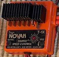
When originally building my TOMSE I wanted to use my Novak1 ESC only later to find out it was not working.
First I tried to look for any info on early Novak repairs and pretty much drew a blank.

The ESC showed no visible signs of parts that had failed.
When in a system with a known good receiver, servo, motor and battery the servo did work.
When first turning on the on/off switch to the on position, the motor does spins very briefly.
No amount of adjustments to the ESC could show any signs of life to the motor.

So may thoughts went like this.
1. Replace the parts that heaviest current draw e.g. the 7 BUZ11 FETs and the 1 L7806C-V voltage regulator.

Before pic of back side of PC board
novak1.0.JPG
After replacing FETs
novak1.6.JPG


Well that did not work :( :? but not totally unexpected.

Next thought will be what the most sensitive component might be.
So I'm setting my sights on the Mitsubishi M51660L "semiconductor integrated circuit for use in servo motor control in radio control applications".
12 of the 14 pins are used in the ESC.
And if I said I found it a bit of a challenge to desolder this I wouldn't be lying.
Arrows denote where IC was soldered.

novak1.1.jpg


IC is ordered.
All thoughts are welcome


Chuck
Hydrodip how to https://www.rc10talk.com/viewtopic.php?f=62&t=42727
When all you have is a hammer everything looks like a nail :wink:

User avatar
GoMachV
Approved Member
Posts: 12187
Joined: Sun Apr 29, 2012 10:31 pm
Location: Twin Falls, ID
Has thanked: 1080 times
Been thanked: 3731 times

Re: Novak1 repair attempt

Post by GoMachV »

The most common thing I experienced working in the hobby shop was the bec going out inside the escs. If you hook up an external battery and either take out the red lead to the receiver or just leave the switch in the off position, with a good or bad bec the esc should operate normally. We used to do some funky jumpering with an external BEC to get the customer going again without spending a lot on a new esc.

Now that I think about it tho you said the servo works so the bec is obviously working. Doh.

User avatar
radioactivity
Approved Member
Posts: 854
Joined: Wed Jan 24, 2018 11:46 am
Location: Dripping Springs Tx
Has thanked: 383 times
Been thanked: 608 times

Re: Novak1 repair attempt

Post by radioactivity »

I tried to cover all my bases first but could have easily overlooked some thing.
So, like usual, I dove in head first.
I am definitely not an EE.

Thanks though.

Chuck
Hydrodip how to https://www.rc10talk.com/viewtopic.php?f=62&t=42727
When all you have is a hammer everything looks like a nail :wink:

JosephS
Approved Member
Posts: 1807
Joined: Thu Mar 23, 2017 5:31 pm
Has thanked: 1203 times
Been thanked: 602 times

Re: Novak1 repair attempt

Post by JosephS »

radioactivity wrote: Fri Sep 15, 2023 4:45 pm I was reading a thread "Repairing Novak 4 esc _ what tools and what parts?" and it got me to thinking.
I took a real good look and decided that needs to be done 'later'

User avatar
juicedcoupe
Super Member
Posts: 3437
Joined: Sun Aug 16, 2020 4:05 pm
Location: Pascagoula, MS
Has thanked: 264 times
Been thanked: 2020 times

Re: Novak1 repair attempt

Post by juicedcoupe »

Could be a bad potentiometer.

I have a Futaba esc that acts stupid, kinda like that.
Always looking for new and interesting ways to waste money.

User avatar
radioactivity
Approved Member
Posts: 854
Joined: Wed Jan 24, 2018 11:46 am
Location: Dripping Springs Tx
Has thanked: 383 times
Been thanked: 608 times

Re: Novak1 repair attempt

Post by radioactivity »

That is a good thought Juicedcoupe.

I just tried to see if there were any glitches to be found.
I could only read the 100k on the right (speed end point) pot. It seems fine even in the circuit.
Can't read left neutral pot, but it does vary when turning the pot.
Both pots do feel surprisingly smooth for the age of the ESC.

I had tried rotating both pots when the ESC was powered on with the trigger pulled but the motor did not respond at all.

Thanks for the tip though!

Chuck
Hydrodip how to https://www.rc10talk.com/viewtopic.php?f=62&t=42727
When all you have is a hammer everything looks like a nail :wink:

User avatar
Frankentruck
Super Member
Posts: 3643
Joined: Fri Feb 19, 2021 9:59 am
Location: Texas, USA
Has thanked: 2484 times
Been thanked: 2787 times

Re: Novak1 repair attempt

Post by Frankentruck »

If there's something wrong with the white/signal wire, like at the receiver end, the ESC won't be available to run the motor. I had an ESC that was similar and was fixed by replacing and re-terminating the red/white/black connector plug.
Frankensteined RC10T3 / Franky Jr RC10GT-e (x2) / A+ stamp / Toy Story RC / Graphite replica / B1.5 BFG 5LTi / Clonewald / Hyper Hornet

"I love the effort, but it sure looks like you took the long way around to a tub again"

User avatar
radioactivity
Approved Member
Posts: 854
Joined: Wed Jan 24, 2018 11:46 am
Location: Dripping Springs Tx
Has thanked: 383 times
Been thanked: 608 times

Re: Novak1 repair attempt

Post by radioactivity »

Thanks Frankentruck

This is the 2nd receiver the Novak1 has been on and I tried it in the servo slot as well. Both of those receivers work with other ESCs but not the Novak1.

So I just ohmed out the 3 wires from the ESC to the receiver plug and they all check OK.
I had replaced the 3 wire harness from the ESC to the receiver so the plug and terminals should have been good. Never hurts to double check.

Thanks again for the input.


Chuck
Hydrodip how to https://www.rc10talk.com/viewtopic.php?f=62&t=42727
When all you have is a hammer everything looks like a nail :wink:

User avatar
radioactivity
Approved Member
Posts: 854
Joined: Wed Jan 24, 2018 11:46 am
Location: Dripping Springs Tx
Has thanked: 383 times
Been thanked: 608 times

Re: Novak1 repair attempt

Post by radioactivity »

I took a couple more pics. One of the IC and a better pic of the board without the IC installed.

With the IC removed the and the voltage regulator moved up the second pic also shows 3 small transistors marked 2785. One faces the forward and the two on the left face the larger FETs.
According to what I find is that they are 2SC2785 transistors.


novak1.8.jpg


novak1.11.JPG

Chuck
Hydrodip how to https://www.rc10talk.com/viewtopic.php?f=62&t=42727
When all you have is a hammer everything looks like a nail :wink:

User avatar
radioactivity
Approved Member
Posts: 854
Joined: Wed Jan 24, 2018 11:46 am
Location: Dripping Springs Tx
Has thanked: 383 times
Been thanked: 608 times

Re: Novak1 repair attempt

Post by radioactivity »

I have found some interesting quirks with this ESC.
If anyone has a Novak NESC1 or NESC1x and can take a picture, it might solve my problem.


After replacing the IC there was no difference :(
However I did find the pinouts on the IC
The #5 pin apparently shows the input. This should be from the receiver???

novak1.15.JPG
novak1.15.JPG (33.18 KiB) Viewed 632 times
novak1.15.JPG
novak1.15.JPG (33.18 KiB) Viewed 632 times


A close look at the board shows no wire or trace going to this pin???

novak1.17.jpg


Also the output wire from the receiver is connected to the cathode of the zener and then goes to ground on one leg of a resistor?????
I think someone else may have been trying their hand at repair.

novak1.18.jpg

Chuck
Hydrodip how to https://www.rc10talk.com/viewtopic.php?f=62&t=42727
When all you have is a hammer everything looks like a nail :wink:

User avatar
Frankentruck
Super Member
Posts: 3643
Joined: Fri Feb 19, 2021 9:59 am
Location: Texas, USA
Has thanked: 2484 times
Been thanked: 2787 times

Re: Novak1 repair attempt

Post by Frankentruck »

PXL_20230925_210314219.jpg
Frankensteined RC10T3 / Franky Jr RC10GT-e (x2) / A+ stamp / Toy Story RC / Graphite replica / B1.5 BFG 5LTi / Clonewald / Hyper Hornet

"I love the effort, but it sure looks like you took the long way around to a tub again"

User avatar
radioactivity
Approved Member
Posts: 854
Joined: Wed Jan 24, 2018 11:46 am
Location: Dripping Springs Tx
Has thanked: 383 times
Been thanked: 608 times

Re: Novak1 repair attempt

Post by radioactivity »

Thanks so much Frankentruck!!!!

Can you see the open hole that is near the #5 leg of the IC? Or is there some thing else there.
It is blocked by the blue "lollypop" looking blue capacitor.
closeup.jpg
and if you can a pic of the other side of the board

Thanks again so much!

Chuck
Hydrodip how to https://www.rc10talk.com/viewtopic.php?f=62&t=42727
When all you have is a hammer everything looks like a nail :wink:

User avatar
Frankentruck
Super Member
Posts: 3643
Joined: Fri Feb 19, 2021 9:59 am
Location: Texas, USA
Has thanked: 2484 times
Been thanked: 2787 times

Re: Novak1 repair attempt

Post by Frankentruck »

PXL_20230925_213629963.jpg
.
PXL_20230925_213709310.jpg
Frankensteined RC10T3 / Franky Jr RC10GT-e (x2) / A+ stamp / Toy Story RC / Graphite replica / B1.5 BFG 5LTi / Clonewald / Hyper Hornet

"I love the effort, but it sure looks like you took the long way around to a tub again"

User avatar
radioactivity
Approved Member
Posts: 854
Joined: Wed Jan 24, 2018 11:46 am
Location: Dripping Springs Tx
Has thanked: 383 times
Been thanked: 608 times

Re: Novak1 repair attempt

Post by radioactivity »

Thanks again!

Interesting... The white signal wire is connected to the #5 on the IC.
But only by soldering across 2 separate copper pads. This is shown in your pic inside the red oval that I drew.

closeup.2.jpg

Pic taken showing no connection between white wire output signal from receiver to #5 input to IC on PC board.

novak1.2a.JPG

Chuck
Hydrodip how to https://www.rc10talk.com/viewtopic.php?f=62&t=42727
When all you have is a hammer everything looks like a nail :wink:

Create an account or sign in to join the discussion

You need to be a member in order to post a reply

Create an account

Not a member? register to join our community
Members can start their own topics & subscribe to topics
It’s free and only takes a minute

Register

Sign in

  • Similar Topics
    Replies
    Views
    Last post

Return to “Vintage Electronics”

Who is online

Users browsing this forum: No registered users and 9 guests