The Cradle mounting pics & details. I will be adding descriptions to the photos through the day.
Tools for mod
- Drill Press
- Dremel w/1/4" sanding drum, lots of patience.
- Diagonal cutters
Procedure:
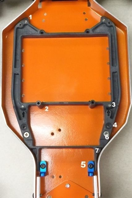
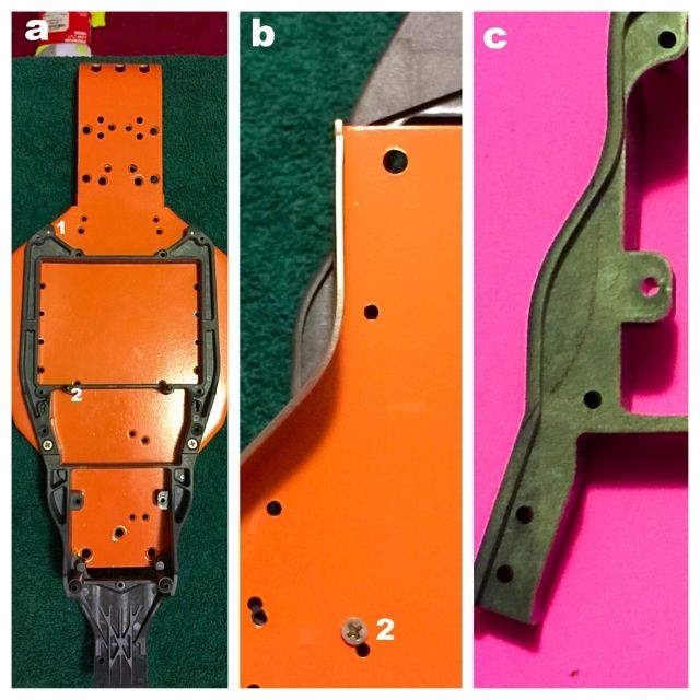
- Photo 1:
I have numbered the screw hole positions, of interest, on the B5m Batt Cradle & Nose.
Hole numbers 1 & 3 must be drilled through the topside side of the Battery Cradle, for Photo 2 needs.
The Battery Hold-down posts holes already go completely through the top and bottom of the cradle.
Note - hole #3 is not a necessary hole. It also requires to be drilled perpendicular, when drilling the hole completely through the battery cradle - the hole is originally an angled hole for mounting to the angled sides of a B5m chassis. And because I see it as being an "optional" mounting point, I have not included its use in these instructions.
1)
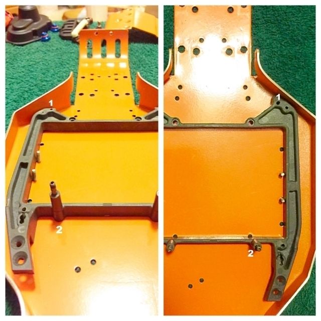
- Photo 2:
I insert (4) 4-40x1/2 FHS into the two non-countersunk holes along the sides of the tub chassis, then set on a flat surface.
Next, I place the B5m batt cradle inside the tub chassis to where the threads of those 4-40 FHS rest on the inside walls of the batt cradle - it helps to center the cradle.
Then, I push the cradle as far back in the Tub Chassis as I can, press firmly on the cradle, and use a drill bit to mark the position of "#1 holes".
Remove the Battery Cradle & 4-40 FHS screws from the Tub Chassis, and drill the #1 holes into the Tub Chassis.
Use (2) of the 4-40 FHS screw to now mount the B5m Batt Cradle inside the Tub Chassis - don't snub the screws down much.
Now, use the drill bit to mark the Battery Hold-Down post mounts, #2 holes.
Remove cradle, Drill the #2 holes in to the Tub Chassis.
2)
- Photo 3:
Segment "a", Assemble and connect the B5m nose piece to the battery cradle.
Next use the #1 & #2 holes to mount the Nose/Cradle assembly to the bottom of the tub chassis.
Segment "b", Now flip the tub chassis right-side up so you can easily see the B5m noseplate overlap next to the neck of the tub chassis.
Use a sharpie marker to outline the curve of the tub chassis neck on the B5m nose piece.
Segment "c", Remove the B5m assembly from the tub chassis, then separate the B5m Nose from the battery cradle. The nose is now ready to trimmed.
The area of the B5m nose piece outside of the sharpie line needs to be trimmed away to mimic the drawn curved line.
NOTE - the closer you get to the sharpie line, when trimming, take more time trimming to match the curve. Trim, then test fit inside the tub chassis, and repeat to desired effect.
3)
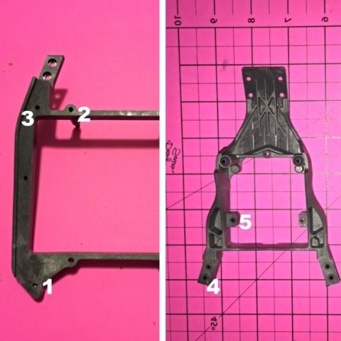
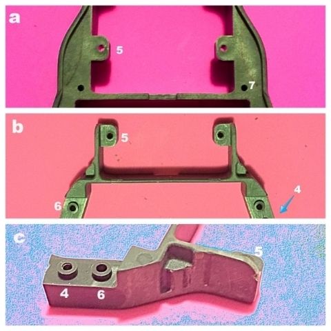
- Photo 4:
Show the Nose piece trimmed to the shape I wanted to go with.
Segment "a", bottom view of nose showing chassis mounting holes #5 & #7. I originally drilled hole #5(servo mounts) to aide in strengthening front/rear tub chassis flex. After lots of time spent evaluating how to mount steering components, I've decided that I should have drilled the #7 hole for use in chassis strengthening instead of the #5 hole.
Segement "b", top view of nose showing hole #5, and #4 & 6.. I wanted at least two points of the nose plate to attach to the tub chassis. To help with reducing flex in the neck of the tub chassis, and to help reduce flex b/t the B5m Nose/Cradle.. I don't really see much difference b/t choosing hole #4 vs #6. I just believe its better to choose two mounting points that are farther from each other, vs closer to each, when wanting to reduce flex.
Segment "c", is only to show the side of the nose after trimming, and what it should look like when done. Hole #'s are for reference only.
4)
-Photo 5:
Finished build of Nose/Cradle assembly mounted in to tub chassis.
5)