RC10B5
Forum rules
This is a catch-all forum for any make and model produced from the year 2000 to present day.
This is a catch-all forum for any make and model produced from the year 2000 to present day.
-
slow_jun
- Approved Member
- Posts: 958
- Joined: Mon Oct 05, 2009 10:59 am
- Location: Manila/Singapore
- Been thanked: 3 times
Re: RC10B5
Finish the build, finish the build, finish the build...... 
“It is more shameful to distrust our friends than to be deceived by them.”
― Confucius
― Confucius
-
RC10th
- Approved Member
- Posts: 4699
- Joined: Sat Feb 16, 2013 9:51 am
- Location: Australia
- Has thanked: 50 times
- Been thanked: 1492 times
Re: RC10B5
If it were a Tamiya it would be discontinued before he finished it.
I was old school - when old school wasn't cool !
-
Orange
- Approved Member
- Posts: 890
- Joined: Fri Apr 24, 2009 12:42 pm
- Location: Chandler, AZ USA
- Been thanked: 1 time
Re: RC10B5
LOL, okay, I'll get back to that prolly tomorrow... I was planning on more today but my wife got the flu and ended up taking care of her.
-
knixdad

- Approved Member
- Posts: 396
- Joined: Thu Jun 06, 2013 3:48 pm
- Location: Califon, New Jersey
- Has thanked: 2 times
- Been thanked: 4 times
Re: RC10B5
RC10th wrote:If it were a Tamiya it would be discontinued before he finished it.
I miss brushed motors in that hazy, everything seemed better when I was a kid, kind of way.
-
scr8p

- Administrator
- Posts: 16734
- Joined: Tue Feb 07, 2006 9:46 pm
- Location: Northampton, PA
- Has thanked: 33 times
- Been thanked: 1192 times
Re: RC10B5
guess we'll have to so that everything the admins/mods say and/or do isn't constantly questioned or challenged.RC10th wrote:Why not start a single "New Car Tech" section stashed away somewhere?
-
scr8p
- Administrator
- Posts: 16734
- Joined: Tue Feb 07, 2006 9:46 pm
- Location: Northampton, PA
- Has thanked: 33 times
- Been thanked: 1192 times
-
Orange
- Approved Member
- Posts: 890
- Joined: Fri Apr 24, 2009 12:42 pm
- Location: Chandler, AZ USA
- Been thanked: 1 time
Re: RC10B5
I hadn't even thought of that... I'll keep an eye on that. So far... Nothing in Bag A-AA,  I might try to get though the next three steps tonight.
-
Orange
- Approved Member
- Posts: 890
- Joined: Fri Apr 24, 2009 12:42 pm
- Location: Chandler, AZ USA
- Been thanked: 1 time
Re: RC10B5
Okay, so on to Bag B, Steps 1-3... Its a good idea to pay a little extra attention to this section. Its not hard, its just it "Could" get messy if your not paying attention.
Parts Removed
Step 1; Steering Knuckles
These are the 2 options for the axles. They can be in-line or trailing. Trailing is called #4 and I could not tell if there was a number on them, however the other ones were clearly #3, so I used the ones without numbers. Once you put it together you can totally see that they are the trailing position. Trailing is what the manual suggests, so that is what I used. They are the bottom ones in this picture.
this is the full assembly of the Knuckles with the axles and More Big Balls:
Step 2; Castor Blocks. Again you have options. Can be 5 degree or 0 degree. The manual said 5 was the standard setup so that is what I installed. More big balls:
Step 3; . Final assembly to Front Arms, Pretty straight forward, hinge pins and screws.
Uprights and Hub Assembly
Uprights to arms
BTW, I decided the Photobucket pics were too big. There is no feasible use for these parts on an old RC10. AND Big Balls!
These are the 2 options for the axles. They can be in-line or trailing. Trailing is called #4 and I could not tell if there was a number on them, however the other ones were clearly #3, so I used the ones without numbers. Once you put it together you can totally see that they are the trailing position. Trailing is what the manual suggests, so that is what I used. They are the bottom ones in this picture.
Uprights and Hub Assembly
-
Orange
- Approved Member
- Posts: 890
- Joined: Fri Apr 24, 2009 12:42 pm
- Location: Chandler, AZ USA
- Been thanked: 1 time
Re: RC10B5
I believe they are all 2". The B4's fit all the way around.Orange wrote:All Turnbuckles are 50mm or 2"
Javier -
RC10 Shelfer, RC10 Worlds Car Runner, RC10T Shelfer, RC10T2 Runner, SC18, JConcepts BJ4, B5M and counting.
RC10T WOIN Build http://www.rc10talk.com/viewtopic.php?f=36&t=32541
RC10 Shelfer, RC10 Worlds Car Runner, RC10T Shelfer, RC10T2 Runner, SC18, JConcepts BJ4, B5M and counting.
RC10T WOIN Build http://www.rc10talk.com/viewtopic.php?f=36&t=32541
-
Orange
- Approved Member
- Posts: 890
- Joined: Fri Apr 24, 2009 12:42 pm
- Location: Chandler, AZ USA
- Been thanked: 1 time
Re: RC10B5
That is basically what I was saying, 
Ya so, that last post was kinda screwy. don't know what happened. So I'm going to re-do it.
Ya so, that last post was kinda screwy. don't know what happened. So I'm going to re-do it.
Re: RC10B5
My bad I read it as a question, after looking at it a second time I realized what you were saying.Orange wrote:That is basically what I was saying,
Ya so, that last post was kinda screwy. don't know what happened. So I'm going to re-do it.
Javier -
RC10 Shelfer, RC10 Worlds Car Runner, RC10T Shelfer, RC10T2 Runner, SC18, JConcepts BJ4, B5M and counting.
RC10T WOIN Build http://www.rc10talk.com/viewtopic.php?f=36&t=32541
RC10 Shelfer, RC10 Worlds Car Runner, RC10T Shelfer, RC10T2 Runner, SC18, JConcepts BJ4, B5M and counting.
RC10T WOIN Build http://www.rc10talk.com/viewtopic.php?f=36&t=32541
-
Orange
- Approved Member
- Posts: 890
- Joined: Fri Apr 24, 2009 12:42 pm
- Location: Chandler, AZ USA
- Been thanked: 1 time
Re: RC10B5
Okay, going back to photobucket. Seems to be way easier I guess.
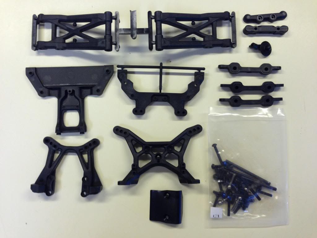
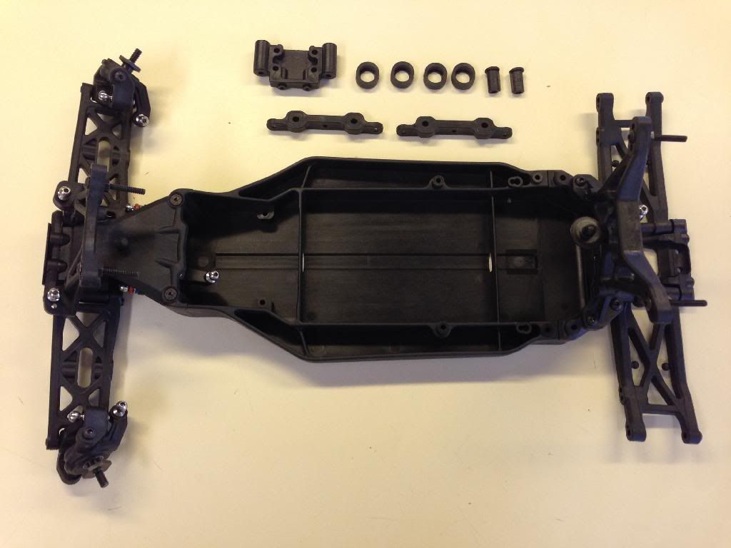
Bag C
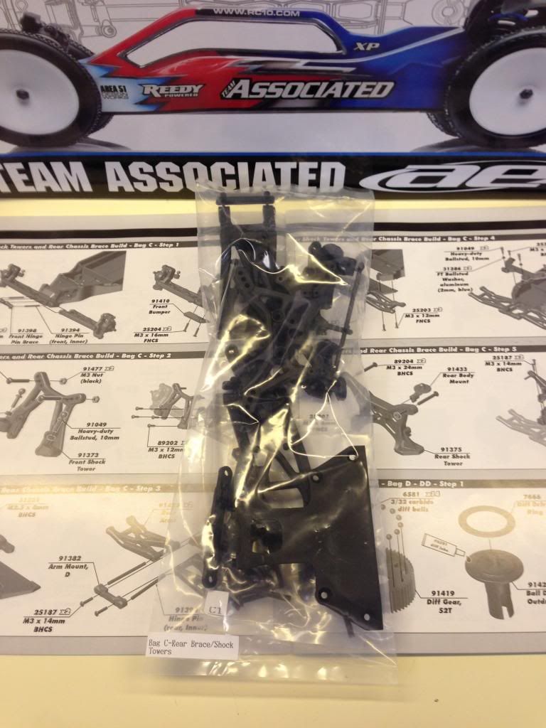
First step is adding the arms onto the front of the chassis. I tried installing the arms as they came out of the bag but they were too tight. With previous B4 buggies I have sanded the black color off of the hinge pins with 600 grit. So I did that and they were still tight, so I ran my Kyosho 3.05 reamer through the hinge pin holes on the front bulkhead. Freed it up nicely.
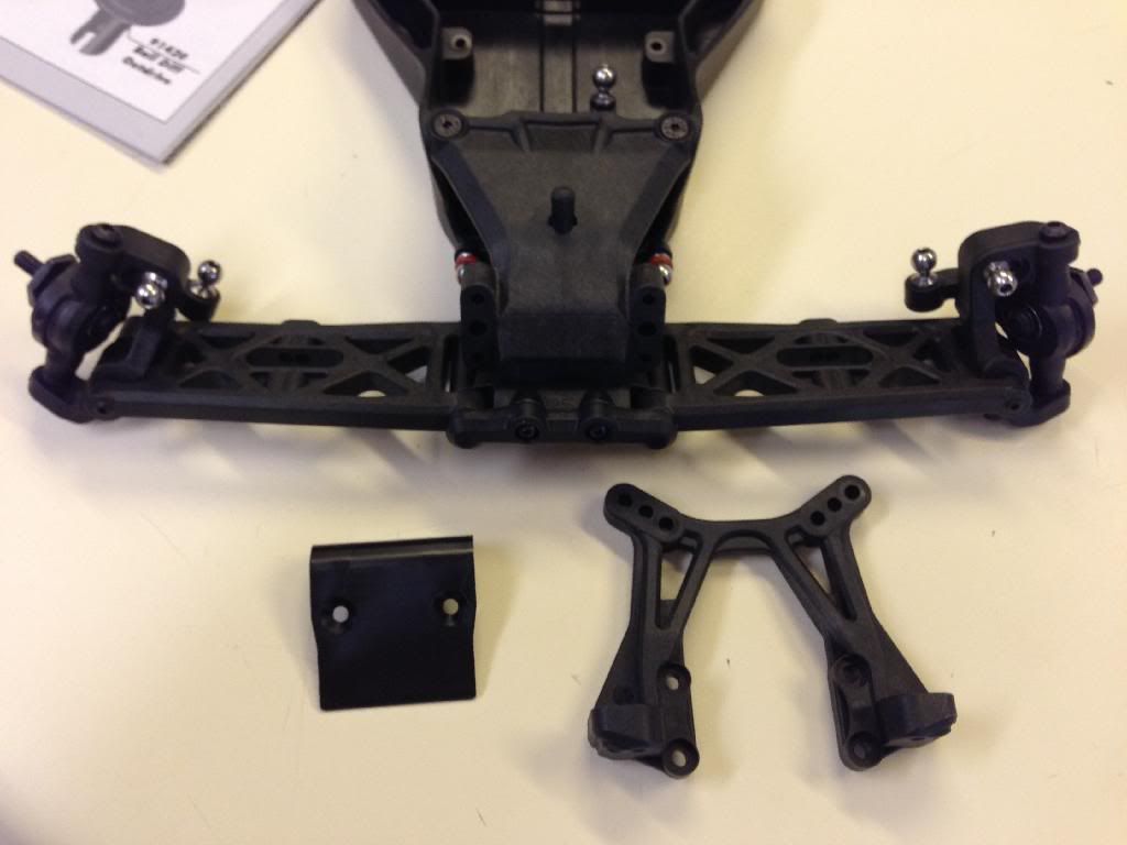
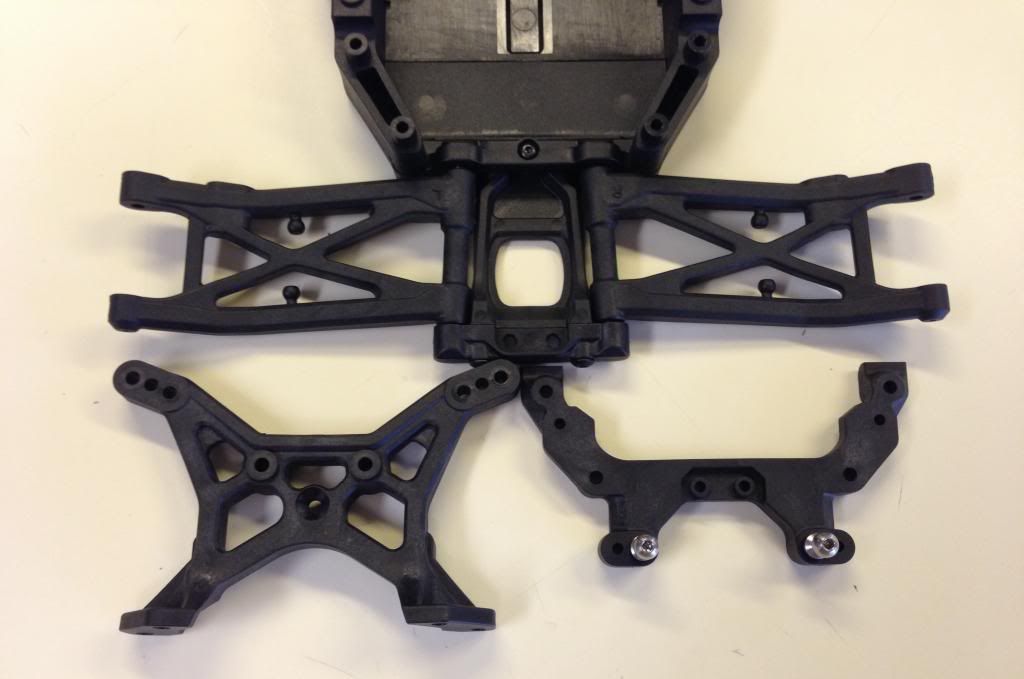
Step 2 is adding the Shock tower w/ball studs and top shock mounting screws installed. This is where I encountered the first problem with the kit. The nuts that hold the screw on are an oddball size. Too big for 5.5mm nut driver, too small for 1/4" nut driver. So I just went into my trusty screw and nut bins and got 4 nice and normal sized nuts. The oddball nut is the example in the next pic:
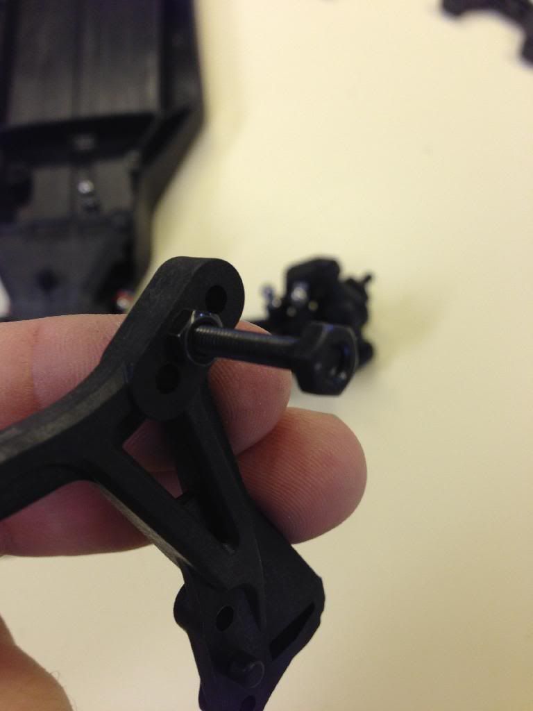
Here is the shock tower installed with Big Balls
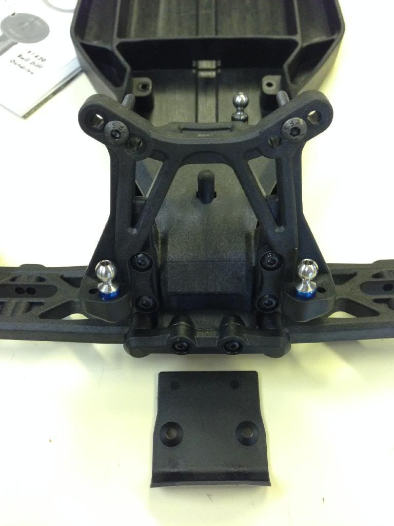
Bumper installed Step 2 complete
Step 3 is installing the rear arms onto the suspension plate. the kit came with three suspension blocks First number is toe and second number is anti-squat From top to bottom, 3/2, 3/1 and 2.5/2.. Same thing with the inner hinge pins. I chucked them up in drill press and sanded them with 600 grit. Also the inner hinge pins on the rear are bigger than 3mm. they are not 4mm so somewhere in-between.
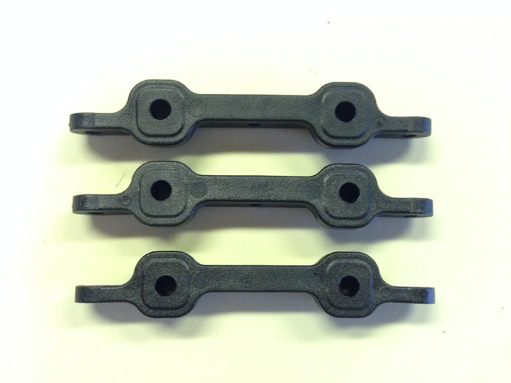
The kit setup is to use 3 degrees toe with 2 degrees anti squat.
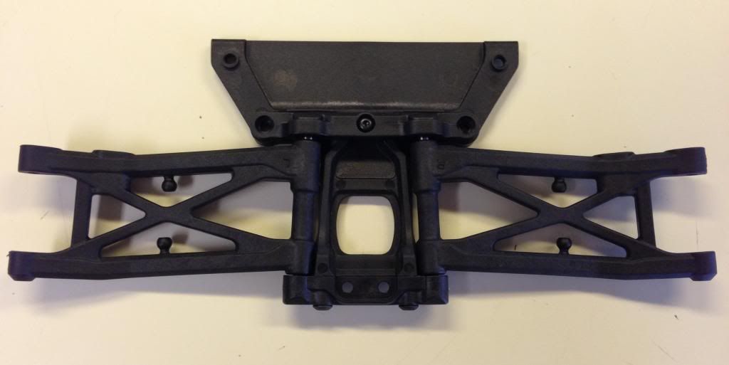
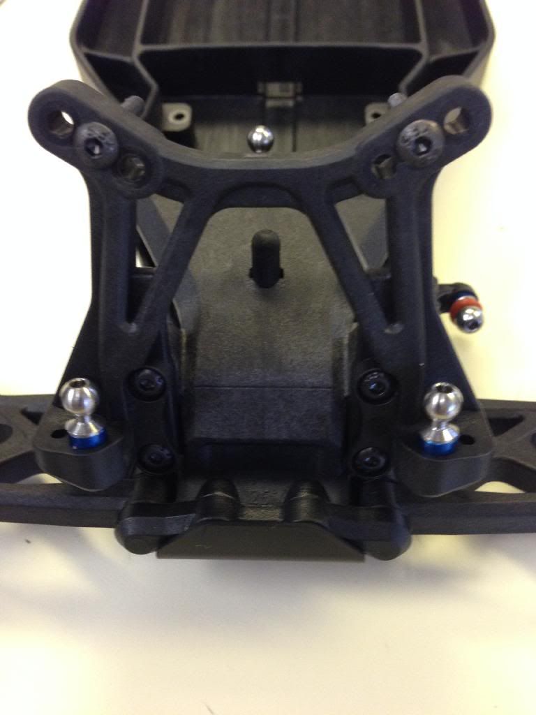
Here is the rear suspension plate added to the back of the chassis with the arms attached. Shock tower top plate and balls in the next step.
Step 4 and 5 was top plate and shock tower install
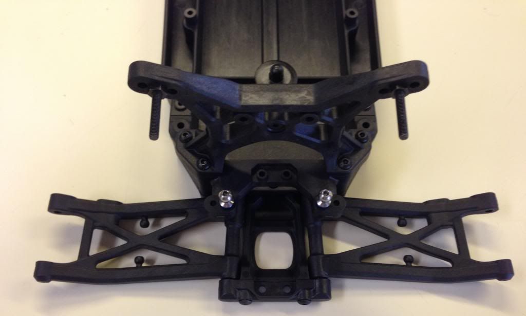
Bag C complete
Bag C


First step is adding the arms onto the front of the chassis. I tried installing the arms as they came out of the bag but they were too tight. With previous B4 buggies I have sanded the black color off of the hinge pins with 600 grit. So I did that and they were still tight, so I ran my Kyosho 3.05 reamer through the hinge pin holes on the front bulkhead. Freed it up nicely.

Step 2 is adding the Shock tower w/ball studs and top shock mounting screws installed. This is where I encountered the first problem with the kit. The nuts that hold the screw on are an oddball size. Too big for 5.5mm nut driver, too small for 1/4" nut driver. So I just went into my trusty screw and nut bins and got 4 nice and normal sized nuts. The oddball nut is the example in the next pic:

Here is the shock tower installed with Big Balls

Bumper installed Step 2 complete

Step 3 is installing the rear arms onto the suspension plate. the kit came with three suspension blocks First number is toe and second number is anti-squat From top to bottom, 3/2, 3/1 and 2.5/2.. Same thing with the inner hinge pins. I chucked them up in drill press and sanded them with 600 grit. Also the inner hinge pins on the rear are bigger than 3mm. they are not 4mm so somewhere in-between.

The kit setup is to use 3 degrees toe with 2 degrees anti squat.

Here is the rear suspension plate added to the back of the chassis with the arms attached. Shock tower top plate and balls in the next step.

Step 4 and 5 was top plate and shock tower install

Bag C complete

-
Orange
- Approved Member
- Posts: 890
- Joined: Fri Apr 24, 2009 12:42 pm
- Location: Chandler, AZ USA
- Been thanked: 1 time

Create an account or sign in to join the discussion
You need to be a member in order to post a reply
Create an account
Not a member? register to join our community
Members can start their own topics & subscribe to topics
It’s free and only takes a minute
Sign in
-
- Similar Topics
- Replies
- Views
- Last post
-
- 99 Replies
- 16573 Views
-
Last post by Jerzi
-
- 7 Replies
- 2246 Views
-
Last post by covell2
-
- 4 Replies
- 1075 Views
-
Last post by lukeeluciano
-
- 2 Replies
- 1084 Views
-
Last post by Breener
Who is online
Users browsing this forum: No registered users and 2 guests