Page 2 of 4
Re: Kyosho Rocky 4wd..... I think?
Posted: Sat Mar 23, 2013 10:48 pm
by RichieRich
Wow. It does look weak. Must have some serious space/clearance issues. There are other cars out there that use a single steering post like that. I wonder if any can be adapted to fit.
Re: Kyosho Rocky 4wd..... I think?
Posted: Sun Mar 24, 2013 6:46 am
by losiXXXman
I don't know if this would help or not, certainly not for a resto mach5, but for a runner... Here's a pic of something I did in an RC10 once, when I was short on parts, but long on inspiration to get the thing running. This one had servo saver action, and obviously used a piece of aircraft ply but worked better than you would think. Substitute some G10/graphite/or aluminum for the ply and maybe you'd have something that would work for the "rocky situation"

.....
Re: Kyosho Rocky 4wd..... I think?
Posted: Sun Mar 24, 2013 10:44 am
by m38joe
this is the wife...I'd say a bumper is a must, since they are jumping these things.... the kyosho falls like a rock!
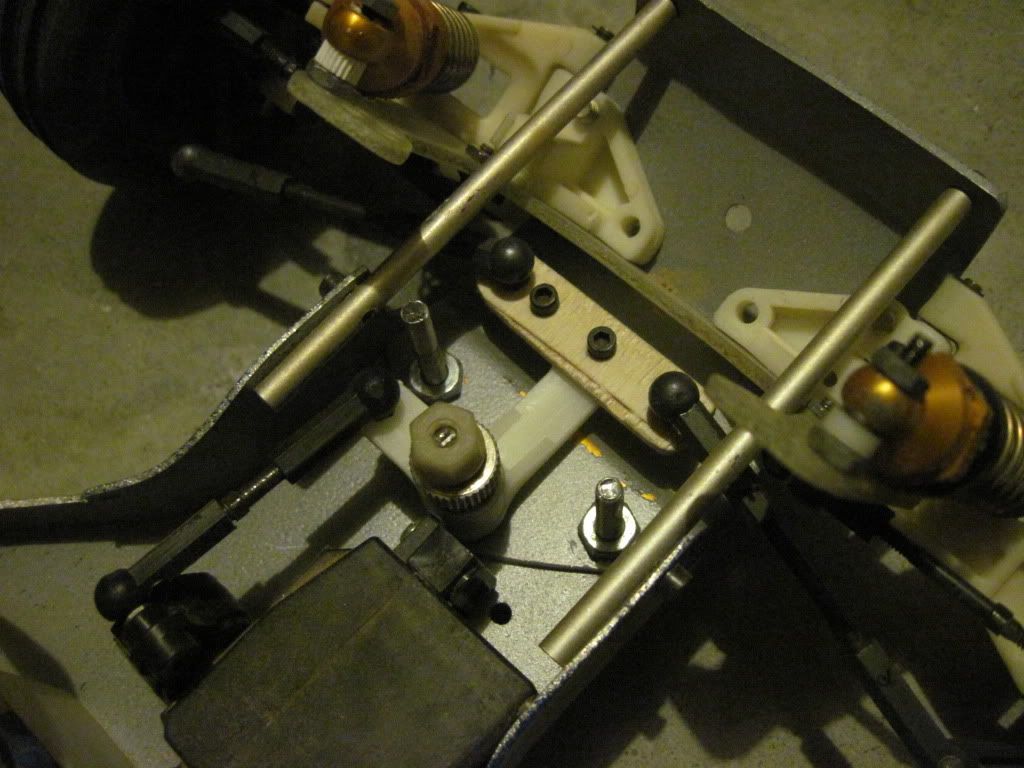
back to the husband.
Here is a few pictures of the bell crank, it's a tight fit.
Re: Kyosho Rocky 4wd..... I think?
Posted: Sun Mar 24, 2013 4:17 pm
by Coelacanth
Certainly not a lot of room with all that mud caked in there. Time for an excavation!

Re: Kyosho Rocky 4wd..... I think?
Posted: Sun Mar 24, 2013 4:22 pm
by m38joe
I knew somebody would get me on the dirty car.
No show cars here
Re: Kyosho Rocky 4wd..... I think?
Posted: Sun Mar 24, 2013 9:38 pm
by turbo scorpion
I would take it out of the car and see if a machine shop can repro it out of aluminum or something. If you wait for it to break they may have a much harder time copying it. Iv also seen people use 3D printing to repro parts. or you can try your hand at copying at home. Iv made some "OK" parts from aluminum using just a drill, hacksaw and a file .
Re: Kyosho Rocky 4wd..... I think?
Posted: Sun Mar 24, 2013 10:04 pm
by GoMachV
the pivot balls snap into it, so metal is out. 3d plastic is still a bit weak. If I didnt have so many projects I would play with it a bit, but I did mock up a g10 bellcrank, and the shortest pivot balls I could find were still too tall
Re: Kyosho Rocky 4wd..... I think?
Posted: Mon Mar 25, 2013 8:44 pm
by RichieRich
Wow, that is a tight fit. It needs a total redesign of the steering system.
Re: Kyosho Rocky 4wd..... I think?
Posted: Mon Mar 25, 2013 8:50 pm
by Coelacanth
It would be easier to see what's going on without all the crud packed in there...

Re: Kyosho Rocky 4wd..... I think?
Posted: Mon Mar 25, 2013 11:14 pm
by RichieRich
I like the dirt. Shows the car is doing what it's designed to do...get dirty and not steer well.
Re: Kyosho Rocky 4wd..... I think?
Posted: Mon Mar 25, 2013 11:40 pm
by markbt73
RichieRich wrote:I like the dirt. Shows the car is doing what it's designed to do...get dirty and not steer well.
So it IS a competitor for the Hotshot, then...
Re: Kyosho Rocky 4wd..... I think?
Posted: Mon Mar 25, 2013 11:45 pm
by GoMachV
We are totally derailing this thread so here are some bellcrank shots of my turbo version


Re: Kyosho Rocky 4wd..... I think?
Posted: Tue Mar 26, 2013 12:58 am
by Coelacanth
gomachv wrote:We are totally derailing this thread so here are some bellcrank shots of my turbo version
I think my bellcrank idea could work there. Note that in my pics, I'm using spacers beneath the bellcrank to make clearance for the balls & cups *beneath* the bellcrank arms. You could simply cut a link from a piece of carbon fiber or aluminum that has the same shape as the section where the rods bend into the balls, with the holes in the same place. Then, some cut-down 3mm screws bolting into some cut-down 4.8mm hex balls on top of the CF or aluminum link, and use Delrin open-ended ball-ends and 3mm threaded tie-rods or turnbuckles in place of the bent threaded rods, which look pretty weak...how do I know this? The lack of clearance with the regular Optima links and the link attached to the steering servo is very similar. There's very little clearance there and I had to use an open-ended ball-end (not a cup) and a hex ball that I'd cut most of the base off, to get everything to clear.
Of course, if I had it in my hands I'm sure I could make it work, just with a bellcrank like the one I'm using for OptiMutt, some 4.8mm hex balls and Delrin open-end ball-ends and a drill.

It'd work way better than that weak, bad design, with less slop, less wear & tear, and less need to rely on hard-to-find parts like that weird-ass steering assembly.
gomachv, can you get me an exact measurement of the amount of space between the top of the aluminum chassis plate and bottom of the chain/gearbox, whichever is lower, in millimeters?
Re: Kyosho Rocky 4wd..... I think?
Posted: Tue Mar 26, 2013 1:25 am
by Coelacanth
Check out the aluminum L-shaped piece in this steering assembly, that would pretty much replace that whole black plastic hodge-podge...it'd be some work and certainly not shelf-queen material, but for a runner, it'd be do-able.
http://www.ebay.ca/itm/Tamiya-F104-or-F103-Exotek-billet-RACE-F1R-steering-crank-set-ships-worldwide-/300645808651?pt=US_Radio_Control_Control_Line&hash=item45ffe2fa0b
That and a few bearings, mounting screws, cut-down 4.8 mm hex-balls and Delrin open-ended ball-ends and you'd be sporting a new alloy, slop-less, durable steering system. A few pics for reference...
Re: Kyosho Rocky 4wd..... I think?
Posted: Tue Mar 26, 2013 1:29 am
by GoMachV
I will get you that measure, but I will also say that with my g10 plate (.062) and threaded zero height balls (the ones they used on the tie rods) there was not enough height for it to fit. The design they used looks to be an afterthought but is the most compact way to do it. I like marks idea of a sliding rack, however a custom works would never fit. It would have to be a flat stock with straps if it was to have a chance. If I can round up a tc3 rack it may be able to be shaved down to fit. That also presents a problem on a plastic chassis car tho, as there is no place for the servo.
I know there is a way but the way I design it has to be repeatable and use easy to source. My biggest issue is that I also want it period correct using what they had back in that era, building one with a 3d printer isn't my cup of tea either.